
As seen on


As soon as Framework announced their Framework 12 Laptop, I new I had to make controller expansion cards and turn it into a Steamdeck(-style handheld gaming computer).
About the Framework 12
Framework are a computer company that focuses on making repairable, upgradable modular laptops (and now desktops) and one of their defining features is their expansion card system. Unlike most laptops, the I/O of the laptop are modular; as a part of a laptop that undergoes some of the most wear, it’s great that these can be easily replaced The modularity also allows each laptop to fit its users needs. Some people might need all USB-A ports, others might want to run 4 displays and others still might opt for 4TB of extra space to run a NAS. In any case, Framework were also kind enough to opensource the design of their expansion cards, releasing 3D models as well as PCB files. They really encourage creators & developers to make whatever accessories they please.
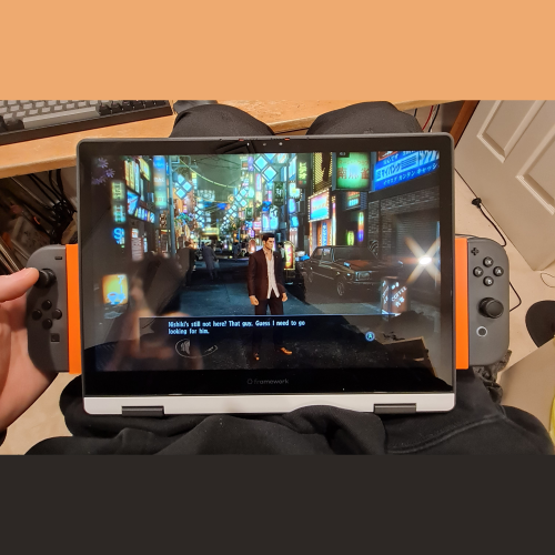
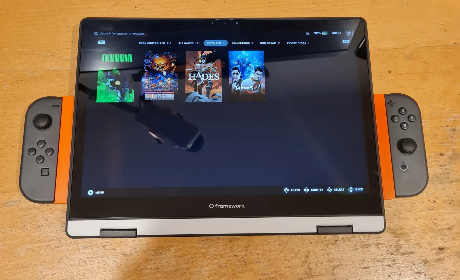
While the motherboards for their Framework 13 has been used in many many handheld gaming PCs, such as the popular Beth Deck, their new Framework 12 is a 2-in-1 laptop that folds into tablet mode. This makes it perfect for attaching controllers to the sides and turning it into a handheld.
Exploring Custom Controllers
Initially, I started designing custom controller expansion cards similar to Wiktor_Tomanek’s Joystick Modules. However, my expansion cards would have to face the other side of keyboard as in tablet mode (because keyboard faces down). Also I found the lack of shoulder buttons on his modules would severly limit the types of games you could play using them.

While I had decided on using PSP joysticks and tactile switches like in the beautiful Nils_Schulte’s PSP Joystick Expansion Card, I started by designing a test pcb using jump pads instead of buttons to verify ESP32 functionality with the cheapest possible PCBs. As I don’t currently have the ability to do SMD soldering at home, I’d have to get them assembled by my PCB manufacturer. However, when I got the quote for it (from JLCPCB) the price was way too high for a one-off and I started looking for alternatives.

Why Joycons?
I started looking for existing controllers that I could make adapters for instead and found that Joycons were perfect for my use case. While not the most ergonomic of controllers and being infamous for stick-drift, they’re a complete package:
- All buttons you need for most games (shoulders included)
- Rumble motors
- Gyro control (for people that like to use it)

After confirming they have full Steam support, I bought a pair as well as a 3rd party charging grip. The charging grip allowed me to copy the dimensions of the Joycon rails as well as let me reverse engineer the charging circuit.
Reverse Engineering the Charging Circuit
Step 1: Identify components

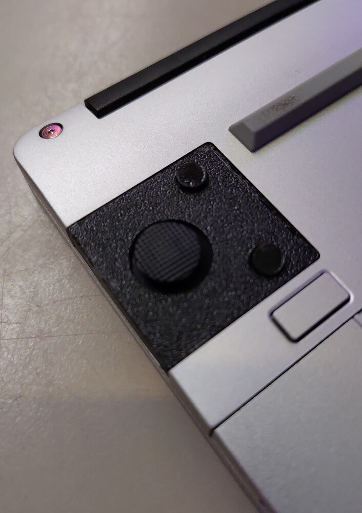
Start by identifying all the components on the circuit board. The designers of this PCB were kind enough to label all the components with IEEE reference designators but here are some general rules to help identify SMD components.
Firstly, having a PCB reference ruler is not essential but incredibly helpful for newcomers. Some components have markings (letters and numbers on them) and ALLDATASHEET.NET is an invaluable resource for looking them up. Often a component of a different type will share the same marking (for example, there’s both a diode and MOSFET marked SS12) so make sure to look for the correct component type. Once you have a datasheet, you can look for the exact component or one with equivalent specifications.

LEDs have translucent pieces and when you plug the device in, they should light up (obviously). You can measure their forward voltage while they’re lit up. The specifications to look out for are package, color and forward voltage.
Resistors are black components with numbers on them. Unlike their through-hole counterparts which use colored bands to indicate values, SMD resistors usually use 3 Digit EIA codes. The first 2 numbers indicate significant digits and the third is a multiplier. “R” is used to indicate a decimal point. The specifications to look out for are package and resistance.
Capacitors are the orange colored components that have no labels. These were the hardest to identify. I desoldered them and measured their capacitance with the capacitance meter function of my multimeter. I don’t think there’s any other way to identify them; make sure to desolder them first because the capcitance of the rest of the circuit will affect your reading (I did get some inconsistent readings so I’m not sure if the capacitances I got are correct). Because this step requires desoldering, do this step last. The specifications to look out for are package and capacitance.
Transistors and MOSFETs are (usually) 3 legged black components with markings on them. The top of a datasheet should identify whether your 3 legged component is a BJT transistor (it might just be labelled NPN or PNP) or a MOSFET. Note that MOSFETs often come in larger packages that combine multiple MOSFETs such as “4 P-Channel” or “1 N Channel + 1 P Channel”.
The BJT specifications to look out for are NPN/PNP, collector-emitter voltage, collector current and power dissipation. The MOSFET specifications to look out for are N-channel/P-channel, drain to source voltage, continuous drain current and power dissipation.
Diodes/Schottky diodes are often larger black components with markings on them as well a solid line on one end indicating forward direction. The specifications to look out for are DC reverse voltage and rectified current.
Fuses are usually larger black components with markings on them but unlike diodes, they don’t have a line indicating direction. It helps to know that fuses found in small electronics are usually resettable fuses. Instead of burning out under extreme currents, they trip and reset after cooling down. The fuse on this circuit was labelled “FH” and after realising I was looking for a resettable fuse, I finally found its datasheet but it was formatted like garbage because it was machine translated from Chinese. There was a table with columns just labelled with letters which isn’t explained anywhere in the datasheet; I eventually figured out that the first table is only relevant for matching markings to part numbers, which are used in the other tables. The specifications to look out for are hold current, trip current and max voltage.
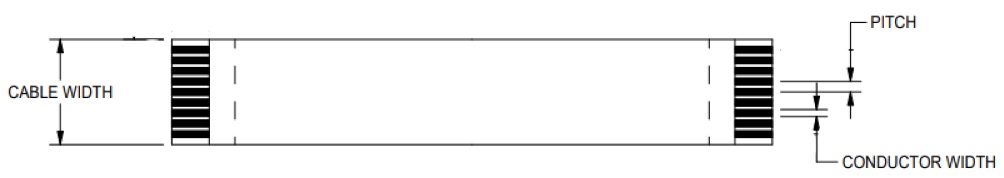
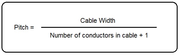
Ribbon cable sockets, or Flexible Printed Circuit (FPC) connectors as they are known in the industry, are pretty straight forward to identify (they have a ribbon cable coming out of them). Using a pair of calipers and formula below, measure the pitch and number of conductors in the cable. These 2 values are the only specifications you need.
USB-C ports are also straight forward to recognise. The specifications to look out for are male/female (critical) and number of contacts. The pinout should be standard but if not, it will be really obvious in the next step.
Step 2: Follow the Traces
As this is only a 2 layer PCB, you can follow the traces by eye but for complicated circuits or multi-layer boards the best way to follow the traces is to desolder everything and check continuity between every component. I did that for good measure.

For USB-C, having some surface knowledge of the standard helps you sanity check your results. VBUS is positive voltage, GND is ground and CC1/CC2 specify the voltage required by using different resistors to ground (USB-C can be plugged in in either direction so there’s 2 but since both directions should get the same voltage, they’re connected here). 5.1KΩ corresponds to 5V which is typical for usb electronics (it’s what USB-A uses).
The final schematic I developed is below.

However as mentioned earlier, having custom SMD assembled PCBs is a bit too expensive for me at the moment so I decided to just make dummy Joycon holders without charging.
Joycon Holder 3D Model

The 3D model for Framework expansion cards is available from their Github repo. I measured dimensions off of the charging grips I disassembled. An important feature of the rail is the small notch which acts as the locking mechanism.
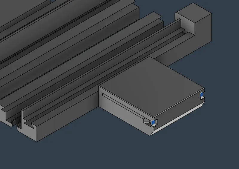
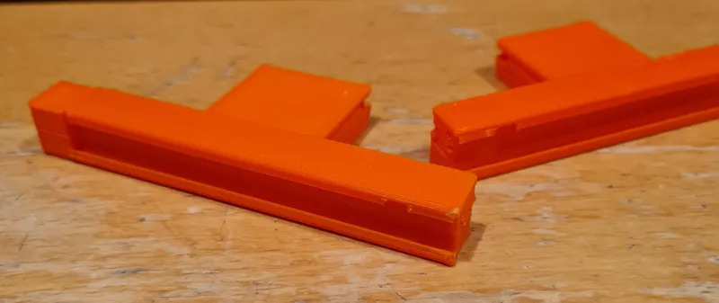
As always, I designed them to print without (auto-generated) supports. Each expansion card comes in 2 pieces that join via a long dovetail. The bigger pieces also have a small built in support (highlighted in blue above) to avoid the need for auto-generated supports.
Future Improvements
I do want to come back to this project at some point and make some improvements:
- The expansion cards currently block the ports next to it as well as the power switch and audio jack
- The rails should be raised up a little so the laptop can lie flat, the triggers currently prop it up a little; this might also move the controllers a bit closer to the center of mass, making the whole device to be easier to hold
- Light channels to see the pairing LEDs would be nice
- Charging circuitry
As for the gaming performance on my Framework 12 (i5, 32GB), it runs Hades fine, Enter the Gungeon doesn’t seem to like my controllers, Yakuza 0 runs fine with lowered graphics (Resolution 1152×720, vsync disabled, quality low) and I’ve yet to try Awaria but I don’t expect it to be too demanding.
Leave a Reply