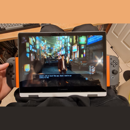
Category: 3D Print

  • HTTP 418 (Proof of Concept)

    If you’ve browsed the internet for a while, you’d prolly be familiar with the HTTP status code “404 Not found” but have you ever come across “418 I’m a teapot“? This code was an April Fool’s joke that got codified into the protocol and it inspired me to make a voice assistant in a teapot that only replies in HTTP status codes.

    The actual Melitta teapot the Utah teapot was modelled after

    The choice of teapot models to use had only one obvious answer. The Utah teapot is a standard reference test model used in 3D modelling and is used as an in-joke in the computer graphics community. I used jharris’ Utah Teapot model as a base for my project. It’s a recreation of the teapot based on the original drawings by Martin Newell and compressed into the iconic 4:3 ratio.

    My idea of the final product to be a teapot where the lid opens up and a small screen pops out to display a 3 digit HTTP status code. However, due to budget reasons, for now I have to settle for a static label instead.

    The curves of the teapot meant the servo had to be installed at an angle. A drive gear, rack and pinion then converts the rotation into linear motion. The lid is hinged to add secondary motion to the teapot and give it a bit more life. Note the red center “screen” comes in 2 pieces: a main body and a thin panel (the thin rectangle in the cross-section). This feature is so that a layer pause can be used to make a perfect overhang. I’m also really proud that the lid snaps onto the top of the center screen; using metal dowels has really expanded my capabilities for making hinges (they’re so much better than bolts).

    In my final design, I want the teapot to be able to run speech recognition and reply accordingly. After a bit more research, it appears that there still aren’t discrete voice recognition modules for microcontrollers that can transcribe everything; there’re only modules that listen out for a set of key words and phrases, intended for home automation. This means I’ll have to run the program on a SBC like the Raspberry Pi Zero. Therefore, I’d most likely be using Python for this project.

    While I could train or tune an LLM to generate replies, it seemed much too overkill for a chatbot that only responds in 3 digit codes. Inspired by ELIZA, the first natural language processing computer program, I decided to hardcode a bot that looks out for certain words or phrases to emulate language comprehension. It’s a bit cheeky and also not very smart but I hope putting it into an animatronic body would create a better illusion of life.

    while True:    
        input_text = input("ask the teapot: ")
        http_code = generate_response(input_text)
    
        if prev_output == http_code and prev_output != 508:
            http_code = 208
        prev_output = http_code
    
        translate_to_text(http_code)

    Model available on Printables here.
    Code available on Github here.

  • Blowback Portal Gun (Proof of Concept)

    As far as I know, no one has ever attempted to create an Aperture Science Quantum Tunneling Device (The Portal Gun from Portal) with a blowback mechanism. So I created a very rough prototype to remedy this.

    There are plenty of recreations of the iconic item from Valve‘s masterpiece ranging from the official Neca Replica, to handmade props to 3D printed designs. Most designs include lights and sounds operated with toggles or tactile switches. However, all of them are static and do not move when firing. Personally, I find that the lack of tactile feedback makes these props feel like toys that don’t quite capture the feeling of the game.

    Advertisement
    3rd Person Gameplay
    1st Person

    In the advertising materials as well as in 3rd person (which can only be accessed through mods and console commands) the portal gun is shown to have no moving parts. However, in the default 1st person perspective, the portal firing animation clearly contracts the device after each shot. This is especially obvious when exporting the models and animations in Blender and viewing from the side.

    Portal Gun Firing Animation
    Images provided by u/IAmLexica

    The blowback mechanism used was inspired by Hasbro’s Transformers Robot Weapons Bumblebee Plasma Cannon (discontinued). Pulling the trigger of an internal handle extends the front of the cannon until it reaches the end and snaps back to its original length.

    Bumblebee Plasma Cannon Toy

    However, this mechanism had to be heavily modified for my design. The portal gun contracts instead of extending when firing so the mechanism had to be reversed; I used a rack and pinion system instead of a lever so that the handle of the device looks the same as the game model; I used rubber bands instead of springs.

    Portal Gun Blowback Prototype CAD

    As this was only a prototype, I used EVARATE’s Portal Gun V2 as a base and only remodeled the body, handle and middle channel. I also only printed the major pieces of the model (small & large cover plates and nozzle) to achieve silhouette of the device as I plan on revisiting this project in the future.

    In testing, my prototype flexed considerably as it was made almost entirely of PLA; the bending made the mechanism unreliable. A full replica would weigh even more so some sort of reinforcement and linear bearings would be necessary. After surveying for feedback, the another point raised was that the reciprocating motion was too fast. Solving this would involve a dampener of some kind such as a gas strut. Regardless, it appears that the mechanism needs be completely restarted from the ground up.

    On another note, while EVARATE’s model is aesthetically pleasing, there are some improvements I would like to make. When overlaying the game model, the proportions are a bit off and I would like my replica to be as accurate as possible. The construction of the model requires glue on almost every joint. Ideally, I would like the model to come together using proper threaded fasteners for easier repair and maintenance.

    Not only is the mechanism unreliable and only successfully firing every 1 in 5 trigger pulls, but the model is impossible to assemble. I overlooked the assembly process and had to carve pieces out with a knife to make them slide into each other.

    This project will be shelved for the time being and I will not be publishing the files but I plan on releasing my final design in the future.

  • Framework 12 Joycon Rail Expansion Card

    As seen on

    pcgamer favicon
    digitrendz favicon

    As soon as Framework announced their Framework 12 Laptop, I new I had to make controller expansion cards and turn it into a Steamdeck(-style handheld gaming computer).

    About the Framework 12

    Framework are a computer company that focuses on making repairable, upgradable modular laptops (and now desktops) and one of their defining features is their expansion card system. Unlike most laptops, the I/O of the laptop are modular; as a part of a laptop that undergoes some of the most wear, it’s great that these can be easily replaced The modularity also allows each laptop to fit its users needs. Some people might need all USB-A ports, others might want to run 4 displays and others still might opt for 4TB of extra space to run a NAS. In any case, Framework were also kind enough to opensource the design of their expansion cards, releasing 3D models as well as PCB files. They really encourage creators & developers to make whatever accessories they please.

    While the motherboards for their Framework 13 has been used in many many handheld gaming PCs, such as the popular Beth Deck, their new Framework 12 is a 2-in-1 laptop that folds into tablet mode. This makes it perfect for attaching controllers to the sides and turning it into a handheld.

    Exploring Custom Controllers

    Initially, I started designing custom controller expansion cards similar to Wiktor_Tomanek’s Joystick Modules. However, my expansion cards would have to face the other side of keyboard as in tablet mode (because keyboard faces down). Also I found the lack of shoulder buttons on his modules would severly limit the types of games you could play using them.

    While I had decided on using PSP joysticks and tactile switches like in the beautiful Nils_Schulte’s PSP Joystick Expansion Card, I started by designing a test pcb using jump pads instead of buttons to verify ESP32 functionality with the cheapest possible PCBs. As I don’t currently have the ability to do SMD soldering at home, I’d have to get them assembled by my PCB manufacturer. However, when I got the quote for it (from JLCPCB) the price was way too high for a one-off and I started looking for alternatives.

    Framework Controller Module Test Schematic

    Why Joycons?

    I started looking for existing controllers that I could make adapters for instead and found that Joycons were perfect for my use case. While not the most ergonomic of controllers and being infamous for stick-drift, they’re a complete package:

    • All buttons you need for most games (shoulders included)
    • Rumble motors
    • Gyro control (for people that like to use it)

    After confirming they have full Steam support, I bought a pair as well as a 3rd party charging grip. The charging grip allowed me to copy the dimensions of the Joycon rails as well as let me reverse engineer the charging circuit.

    Reverse Engineering the Charging Circuit

    Step 1: Identify components

    Joycon Charging Grip Close Up

    Start by identifying all the components on the circuit board. The designers of this PCB were kind enough to label all the components with IEEE reference designators but here are some general rules to help identify SMD components.

    Firstly, having a PCB reference ruler is not essential but incredibly helpful for newcomers. Some components have markings (letters and numbers on them) and ALLDATASHEET.NET is an invaluable resource for looking them up. Often a component of a different type will share the same marking (for example, there’s both a diode and MOSFET marked SS12) so make sure to look for the correct component type. Once you have a datasheet, you can look for the exact component or one with equivalent specifications.

    Adafruit PCB Ruler v2 – 6″

    LEDs have translucent pieces and when you plug the device in, they should light up (obviously). You can measure their forward voltage while they’re lit up. The specifications to look out for are package, color and forward voltage.

    Resistors are black components with numbers on them. Unlike their through-hole counterparts which use colored bands to indicate values, SMD resistors usually use 3 Digit EIA codes. The first 2 numbers indicate significant digits and the third is a multiplier. “R” is used to indicate a decimal point. The specifications to look out for are package and resistance.

    Capacitors are the orange colored components that have no labels. These were the hardest to identify. I desoldered them and measured their capacitance with the capacitance meter function of my multimeter. I don’t think there’s any other way to identify them; make sure to desolder them first because the capcitance of the rest of the circuit will affect your reading (I did get some inconsistent readings so I’m not sure if the capacitances I got are correct). Because this step requires desoldering, do this step last. The specifications to look out for are package and capacitance.

    Transistors and MOSFETs are (usually) 3 legged black components with markings on them. The top of a datasheet should identify whether your 3 legged component is a BJT transistor (it might just be labelled NPN or PNP) or a MOSFET. Note that MOSFETs often come in larger packages that combine multiple MOSFETs such as “4 P-Channel” or “1 N Channel + 1 P Channel”.

    The BJT specifications to look out for are NPN/PNP, collector-emitter voltage, collector current and power dissipation. The MOSFET specifications to look out for are N-channel/P-channel, drain to source voltage, continuous drain current and power dissipation.

    Diodes/Schottky diodes are often larger black components with markings on them as well a solid line on one end indicating forward direction. The specifications to look out for are DC reverse voltage and rectified current.

    Fuses are usually larger black components with markings on them but unlike diodes, they don’t have a line indicating direction. It helps to know that fuses found in small electronics are usually resettable fuses. Instead of burning out under extreme currents, they trip and reset after cooling down. The fuse on this circuit was labelled “FH” and after realising I was looking for a resettable fuse, I finally found its datasheet but it was formatted like garbage because it was machine translated from Chinese. There was a table with columns just labelled with letters which isn’t explained anywhere in the datasheet; I eventually figured out that the first table is only relevant for matching markings to part numbers, which are used in the other tables. The specifications to look out for are hold current, trip current and max voltage.

    Ribbon cable sockets, or Flexible Printed Circuit (FPC) connectors as they are known in the industry, are pretty straight forward to identify (they have a ribbon cable coming out of them). Using a pair of calipers and formula below, measure the pitch and number of conductors in the cable. These 2 values are the only specifications you need.

    USB-C ports are also straight forward to recognise. The specifications to look out for are male/female (critical) and number of contacts. The pinout should be standard but if not, it will be really obvious in the next step.

    Step 2: Follow the Traces

    As this is only a 2 layer PCB, you can follow the traces by eye but for complicated circuits or multi-layer boards the best way to follow the traces is to desolder everything and check continuity between every component. I did that for good measure.

    Desoldered Charging Grip PCB

    For USB-C, having some surface knowledge of the standard helps you sanity check your results. VBUS is positive voltage, GND is ground and CC1/CC2 specify the voltage required by using different resistors to ground (USB-C can be plugged in in either direction so there’s 2 but since both directions should get the same voltage, they’re connected here). 5.1KΩ corresponds to 5V which is typical for usb electronics (it’s what USB-A uses).

    The final schematic I developed is below.

    Joycon Charging Grip Schematic

    However as mentioned earlier, having custom SMD assembled PCBs is a bit too expensive for me at the moment so I decided to just make dummy Joycon holders without charging.

    Joycon Holder 3D Model

    Joycon Charging Grip Side View

    The 3D model for Framework expansion cards is available from their Github repo. I measured dimensions off of the charging grips I disassembled. An important feature of the rail is the small notch which acts as the locking mechanism.

    As always, I designed them to print without (auto-generated) supports. Each expansion card comes in 2 pieces that join via a long dovetail. The bigger pieces also have a small built in support (highlighted in blue above) to avoid the need for auto-generated supports.

    Future Improvements

    I do want to come back to this project at some point and make some improvements:

    • The expansion cards currently block the ports next to it as well as the power switch and audio jack
    • The rails should be raised up a little so the laptop can lie flat, the triggers currently prop it up a little; this might also move the controllers a bit closer to the center of mass, making the whole device to be easier to hold
    • Light channels to see the pairing LEDs would be nice
    • Charging circuitry

    As for the gaming performance on my Framework 12 (i5, 32GB), it runs Hades fine, Enter the Gungeon doesn’t seem to like my controllers, Yakuza 0 runs fine with lowered graphics (Resolution 1152×720, vsync disabled, quality low) and I’ve yet to try Awaria but I don’t expect it to be too demanding.

    While it’s still just a proof of concept but the models are available on Printables here.

  • Pepe LED Neon Sign

    A friend wanted to decorate their room and suggested a neon Pepe the Frog sign to hang on their wall. I decided to make one for them.

    Initial Research

    The very first step is to find out what LED strips to use. Real neon signs are made using glass tubes filled with neon gas and extremely high voltages but diffused LED strips make for a great substitute. They can be inserted into 3D printed tracks, wired together and mounted on a wall. Much cheaper, lighter, safer and easier to make.

    I found a listing on Aliexpress (apologies if listing goes down) for 12V neon light strips. While the information on the product page does give some dimensional information, they should be taken with a grain of salt as these flexible strips are squishy. Before purchasing the strips, the lengths of each color required should be determined.

    Linework

    The first step was to create vector linework. Vector file formats, such as SVG, stores images as lines and shapes instead of pixels which allows use to manipulate it in CAD (3D design software).

    Using Inkscape, I traced over a reference image using the pen tool to create the linework. I used a 5mm line thickness (while this did turn out to be a more accurate thickness, the product listing does say 6mm) and the limited color palette outlined in the product listing for the LED strips.

    When designing an LED strip sign, it’s important to avoid any sharp corners and curves that are too tight for the strip to bend around. Unfortunately there are no hard rules to this and you’ll have to eyeball it.

    It’s also important to ensure that separate lines are not too close to eachother; I had to switch back and forth from Fusion360 and Inkscape to make many small adjustments to avoid any overlapping tracks but in retrospect, I should have just used a thicker line in the drawing process.

    Also note that because the LED strips have a minimum length per segment, avoid drawing any really short lines.

    The idea is not to trace as accurately as possible but rather try to capture the general shape of the reference picture. Some compromises in accuracy have to be made to ensure the lines are well spaced apart.

    Sourcing Parts

    Once the linework was finalised, a 3D model was created in CAD. The SVG design was imported into Fusion360 and scaled to the correct dimensions; for an unknown reason, the design was being imported with incorrect dimensions and I suspect it may be related to some backend imperial vs metric war. I added a 50mm reference line to the linework design to ensure the correct scaling.

    The lines were thin extruded (see screenshots the next section) to create the LED tracks and I confirmed that none of the tracks would intersect with another.

    Then, I found the length of each line by measuring the total volume of the tracks and dividing by cross sectional area (I couldn’t find a better way to do this so if you know of a better method, please let me know on my comments page). I was then able to order the correct lengths of each color of LED strips.

    The strips are sold with an optional female DC jack. Only one was needed, so only one was ordered with that option. Also as the strips will be cut anyway, it’s more economical to get one big strip than multiple smaller strips of one color.

    With a total length of about 2 meters at 8 Watts per meter (from product listing) and 12 Volts, the total current draw of the sign would be 1.5 Amps rounded up (2 x 8 / 12 = 1.33). I ordered a 2A DC 12V adapter as they only come in 1A increments. While getting an adapter with a very high max current rating would avoid the current calculations, higher current adapters are more expensive, physically larger and less efficient at lower currents. The seller ended up sending me a 4A adapter by mistake but the higher rating meant it was fine to use.

    3D Modelling

    After recieving all the parts, I was able to measure the parts and print out a test piece to confirm the track cross section.

    As aforementioned, the imported linework was thin extruded. I wanted a depth of 8.5mm for the track which would allow just the colored tops of the strips to stick out. To account for a 1mm bottom, I extruded a distance of 8.5+1mm. The strips were 5mm wide and I wanted a wall of 1mm on each side so I set the extrude wall thickness to 7mm. Wall location was set to center.

    After selecting all the top faces of the extrusions, the shell command was used to turn them into tracks. Note that this operation only works if each line segment has no intersections. While using sweep commands on a cross section could work, I found this method to be the most convenient.

    Then a 1mm backing was made by extruding a sketch connecting the outer perimeter of the tracks with smooth lines.

    The final step is to add holes for wiring at the ends of each track. I recommend adding holes at both ends of each track unless you’re certain which side you want the wires to come out of.

    Final Assembly

    The LED strips were cut into lengths to fit each channel. The strips have black lines indicating where the solder contacts are; this is the intended place to cut them. Ideally, the design would be made of lines with lengths that are divisible by the minimum LED strip segment lengths. This is not the case but I prefer the look of having one end of the strip have dead zones rather than leaving the track empty. As long as one end of the strip has solder contacts on them, the sign will work fine.

    The soft diffusion layer of the strips were cut and peeled back so wires could be soldered onto the contacts. The strips were then pushed into the tracks and wires fed through the back. The track dimensions should allow the strips to be held in with friction but use your glue of choice (I recommend hot glue) as needed. For the really tight bends like you see in the pupils of Pepe, I needed to use hot glue to persuade them into the correct shape as they kept trying to spring out of the tracks.

    I used solid core wire for everything but the DC jack. It’s much easier to work with than stranded. Make sure to use 2 separate colors for positive / ground. A short (unwanted electrical connection) between positive and ground can damage the LEDs and power adapter so always use heatshrink on joints. While you can use tape in a pinch, I highly recommend buying proper heatshrink; it’ll really improve the quality of your work and it’s really cheap.

    Models available on Printables here.

  • Lefty HyperX Pulsefire Saga

    Printables is, at time of writing, holding a 3D printed design contest Shape Your Saga: HyperX Mouse. The partner company HyperX tasked participants design parts for their Pulsefire Saga mouse, with emphasis on new top shells for different grip styles. I’ve worked on and off on left handed ergonomic mice and this contest was a great motivation for me to actually finish a design.

    HyperX provided models for the shells and buttons as well as a subtraction body. I started by mirroring the side buttons and joining them with a double lever mechanism. The levers connected to the mirrored side buttons were designed to be able to swing 3.2° while the levers that push the circuit board switches were designed for .5° (I assumed 1.5mm travel, like this Omron switch).

    I flipped the top shell and attached the front hinges. The rear hinges were made into a separate piece for assembly. The subtraction body was used to ensure clearance for everything. The mouse buttons also needed a bit of trimming on the corners as well and I prettied them up as much as possible using fillets.

    Unfortunately, I don’t own a Pulsefire Saga mouse and HyperX haven’t given details on internals so I can’t confirm if this design will work, but if I win a mouse, you can be sure I’ll try it out and iron out any issues. I’ve always wanted a left-handed ergonomic mouse, not because I’m a lefty but because they’re really nice to hold (I have a lefty Logitech MX Master 3S monolith from a postponed project. If I ever have enough disposable income to pull apart a MX Master 3S, I’ll try making a lefty version).

    Anyway, after all that, I rendered it and did a sloppy GIMP job to make a catchy thumbnail for my contest entry.

    Models available on Printables here.

    Update: I did not win any prizes

  • Leatherman Crunch Horizontal Holster

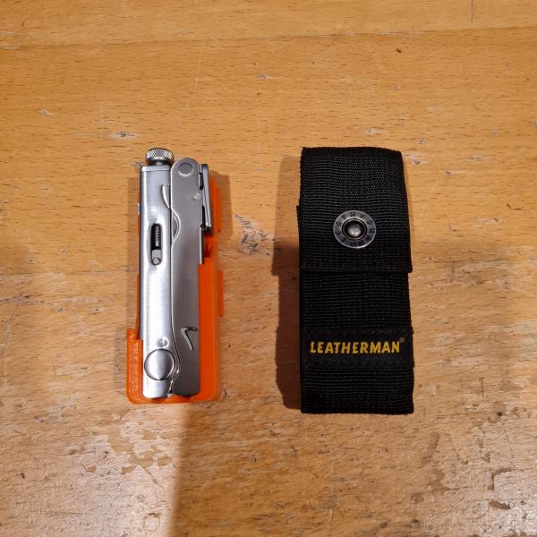
    I made a belt holster for my EDC multitool.

    The Leatherman Crunch

    The Leatherman Crunch is my dream multitool.

    Leatherman Crunch

    It’s the last tool designed by founder Tim Leatherman and what a banger it is. A folding pair of vise grips? As someone who often finds themselves tearing apart plastics and thin sheet metal, I need that ability to progressively chomp down on parts and wrench them apart. The Crunch is an absolute beaut piece of engineering: a competent pair of locking pliers with an adequate selection of tools that folds down into the most compact package among its competitors because its competitors can’t even fold at all. They’re either no more than a regular pair vice grips with a parasitic knife in one handle (Irwin so embarassed of it, it’s not even on their website anymore) or they don’t fold at all (also not listed on the official Kershaw website).

    At about $200AUD, it’s alright for the price; but since it got discontinued – reran – discontinued again, the supply has been funneled down into the hands of collectors who trade them for 3 times the price, only to put behind glass cases. I’m one of the rare second-hand-hunters actually looking to use them (or maybe people who actually use it love it too much to sell them). Not to mention most of them are in the US which insanely hikes up the shipping.

    Then on one fateful day of me idly browsing Ebay on a whim, I found a deal of a lifetime. A Crunch? At MSRP or best offer? In Australia? In NEW CONDITION? From a seller that just signed up and is also selling a bunch of other knives in new condition as well? Yeah it smelt like a scam but with a deal this good and with Ebay and Paypal’s scam protection, I could not pass up on the opportunity. Turns out the seller was some collector’s wife disbanding his knife collection, probably pricing things based off the first result. Needless to say, I was a very happy person when the knife finally arrived.

    Sheath Design Inspiration

    Leatherman Crunch with original nylon sheath

    I’ve never had a Leatherman before and was quite pleasantly surprised by the quality of the included nylon sheath. However, just as I’ve been dreaming about getting a Crunch, I’ve also been dreaming about getting a ZapWizard-style sheath for it (at time of writing, he hasn’t designed one yet and as the Crunch is a niche discontinued product, he probably never will). Just in case someone had already designed something similar, I did some research and only found 2 Leatherman Crunch sheaths on Etsy at time of writing. One is magnetic looks insecure while the other one appears to have unnecessary bulk. Needless to say, I had to design my own so I did.

    Personally, I didn’t need my holster to have tool or bit holders. I feel that a multitool ought to be fully self contained so you don’t have to worry about fiddling around a losing accessories. I think the beauty of ZapWizard’s designs comes from their pragmatism and minimalism; it’s as if the bare tool just sticks onto a belt and I feel that the accessory mounts break that illusion.

    My Design

    Most Leatherman multitools that ZapWizard designs for have spring-operated metal tabs (as part of the tool) that he uses to lock in the tool which allows for a metal on plastic action that’s resistant to wear. In a similar way, I designed in some nubs which engage with the Crunch’s plier head which sticks out when folded. While I didn’t cut out slits to turn it into a compliant mechanism, the tool snaps in satisfyingly and holds the tool reliably. This might eventually wear out the sheath long-term but I want to test my design out for a while to identify other problems as well before addressing it. I want to eventually finalise a design worth committing to nylon sintering like ZapWizard’s.

    It’s a good thing I did test it out for a bit because I quickly identified an issue.

    Leatherman Crunch Horizontal Sheath version comparison

    For the Mk1 (left), I just took measurements of the tool and designed channels that run to the end sheath for the Crunch’s protrusions to slide along. However, after using the sheath on an actual belt, I found myself trying to slide the tool in at a diagonal through the center of the long side rather than sliding it in parallelily (adverb of parallel) from the short side. The sides of the big plier hinge channel prevented me from doing that so for the Mk2, I opened the channel up. I also realised that the plier hinge would never interact with the short open end so I also beefed it up and added a gradual slope. Doing this not only made it possible to slide the tool in diagonally, it also made it much easier to line up the tool to slide it in from the short side as well. Also note that I used 3D honeycomb infill instead for the Mk2 of gyroid because it looks better; my printer is tuned poorly so the infill pattern shows through the surface.

    One embarassing (because a good 3D print should not require supports) thing is that for strength, I had to make the belt loops print with supports. This print orientation used minimal supports while also making the loops strongest. This won’t be relevant for laser sintering though.

    I’m happy with the Mk2 for now but we’ll see where else I can improve for now. Due to the sharp edges of the Crunch bottom one finger release isn’t comfortable at the moment but I’m not sure if this can be addressed. When pulling the tool out, it pops out suddenly and I want to add some features to slow it down like ZapWizard’s sheaths.

    Future Projects

    In terms of other Crunch projects, I want to mod the tools (most of these ideas are from ZapWizard). While I’m incredibly happy with the vice grips (which have seen a lot of use already), the tool selection seems a bit lacking. Currently, the only tool mod that exists for the Crunch is a hammer which just feels wrong; surely whacking the handle sideways into the screw can’t be good for your tool. The serated blade is fine but most of my knifework is with craft blades; I’m looking at making a exacto blade or scalpel holder. There’s 2 flat heads and a 3D Phillips which are fine but I more often use smaller bits so a 4mm precision bit holder (with built-in bottle opener) would be much more useful to me. The existing built-in bottle opener is surpisingly good (barely dents the cap) but it’s part of the smaller flat head. Also I have no use for a file so maybe I could use a T-shank holder and attach a saw.

    Reprint

    My original PLA print started bending and finally snapped after a few weeks so I reprinted it in PETG. It locks in just as well, possibly better, and it also is showing no sign of fatigue. I’ll update this post if it breaks again.

    Model available on Printables here.

  • Horizontal Headphones

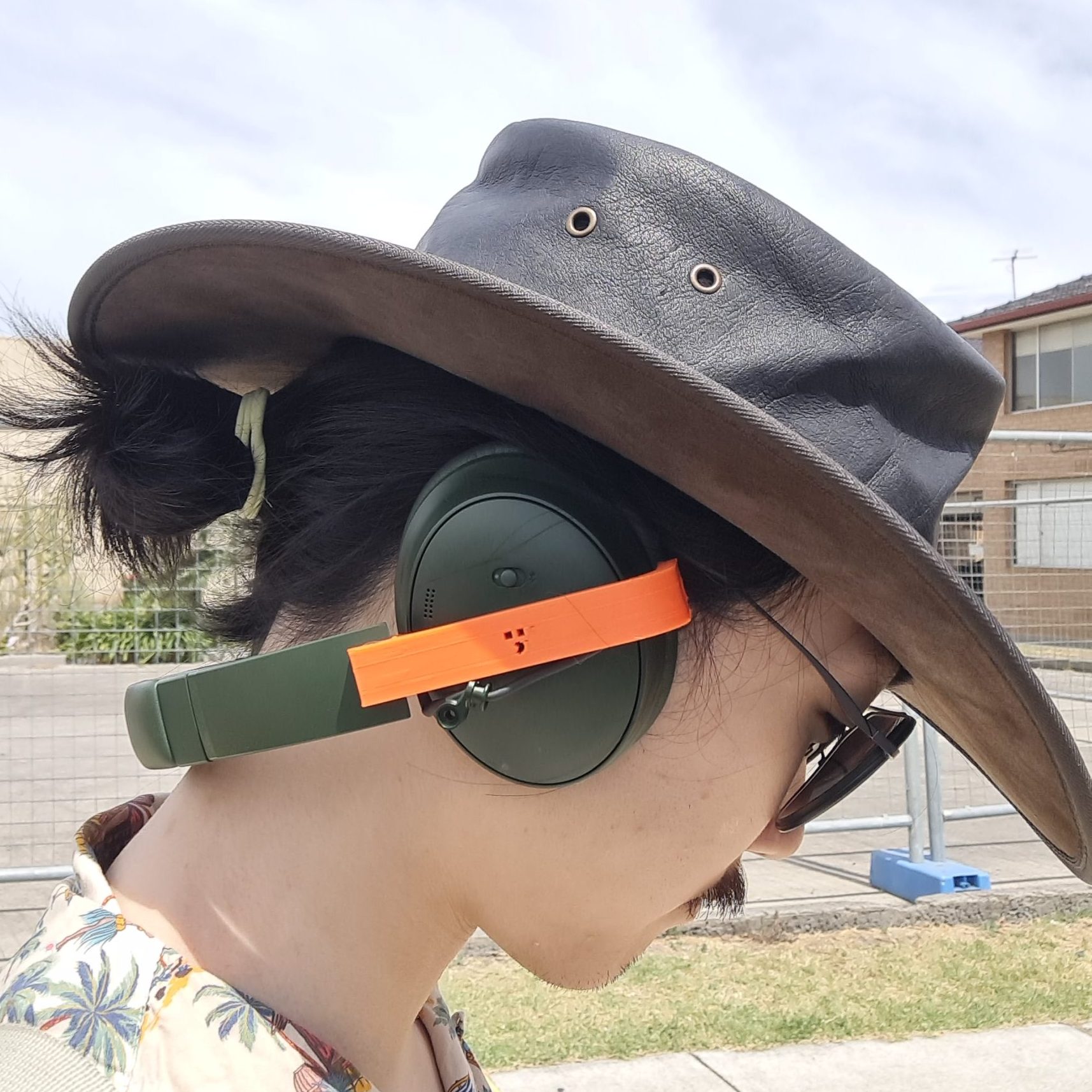
    Here in the sun cancer capital of the world, going outside means I have to choose between wearing a hat or wearing headphones. My favourite hat is a broad brim kangaroo leather hat, while the headphones I put up with are over ears. I prefer them over wireless earphones and the like because they’ll never be as good at noise cancelling without proper ear cups. But I’ve always wondered what if the headband didn’t have to be vertical. The clamping force of headphones seems adequate to keep them on my head so what if it ran horizontally across the back of my head so I could wear a hat on top?

    The biggest block for me from starting on this project was having no idea what shape would comfortably clamp my head. On previous attempts, I made very rough measurements of my head and designed a new headband for a broken pair of headphones I had. I didn’t get very far. I was going to eventually build up to modifying my daily headphones anyway, so I put aside my fears of breaking it and pulled it apart.

    I don’t call Bose QuietComfort’s my favourite headphones because I used to have a pair of QC35 II’s which despite being the older model had much more reliable bluetooth connection that switched between devices more reliably and did not spew static on weak disconnection. Also the anti-SEO marketing team that named the successor to the “QuietComfort 35” and “QuietComfort45” as the “QuietComfort” needs to be fired. There isn’t an iFixit manual for this specific model but the cups hinge on a wishbone shaped part made of 2 pieces. Unscrew the 2 screws connecting them, slide out the inner piece and slowly force out the outer one (it’s flexible). Then I removed the 2 screws on each adjustable section to loosen the upper hinge knuckles as well as the accordioned cable inside. Trying to remove this knuckle piece would involve desoldering or splicing wires which I really didn’t want to do. Luckily the accordioned section of the cable was long enough to stretch across the outside of each earcup towards the back of my head. While I would have freed the cable from the headband, it appeared to be plastic welded into it.

    All I needed to replace in the end was the wishbone pieces which allowed the headphones to hinge in 2 directions: to let it fold and adjust to the shape of the head. One each cup, 2 pins were designed to go where the original wishbone nubs went in; a c-shaped piece would snap over the pins and attach to the headband. Pointing the headband collinearly to the straight of the c-shape fit fine around my head; the ear cups were pointed 10 degrees inward to fit flush over my ears. The headband has springsteel running through it which provides a perfect amount of clamping force.

    While running to reach a traffic light, the c-shape snapped out of the pins (which I lost), leaving an earcup dangling. Getting home, I redesigned it to accommodate self-tapping screws. Note I that I used hex sockets because stripping and camming out of Phillips heads makes me curse at [Henry Ford](https://www.ifixit.com/News/9903/bit-history-the-phillips).

    Horizontal Headphones on Table

    Wearing them for a while now, I think I can see why manufacturers don’t make this as a product. If the clamping is not perfect, the weight rests on the top of the ears; my ears do feel tired if I wear them too long, although most of the weight is supported by clamping. Another downside is that I can’t stretch my neck backwards but I imagine a more form-fitting design would allow me to. Yet another sacrifice my design makes is that the headphones can’t fold anymore and therefore does not fit inside its case. In the future, I hope to get my hands on a 3D scanner and design a better version that fixes these issues as well as properly enclose the cables instead of leaving them hanging out like they do now.

    This project is not in a shareable state so I will not publish the models.

  • Rapid Access Zipper Pull Tab

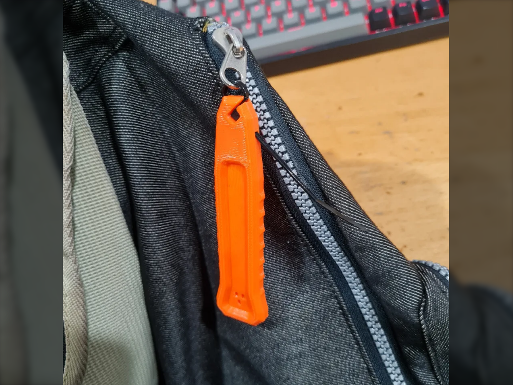
    One of the YouTube niches I binge on are tactical gear reviews. One day I came across PrepMedic’s review of the Vertx Ready Pack and found out about their signature Rapid Access Tab. But when I found out that they went for an outrageous $35 kangaroos, I searched online for a 3D print file for one and surprisingly came up with nothing. So I got to work.

    Essentially, it’s an oversize zipper that makes bags easier to open, which in hindsight, probably be helpful for people with poor motor function such as those with Parkinson’s.

    I wanted it to be as easy to reproduce as possible so instead of using a metal ring or string which can come in various sizes, I decided to use a zip tie because it comes in standard sizes. The way the zip tie fits so snugly into my design is especially satisfying to me.

    Also it appears I made this on Christmas day. An interesting coincidence.

    Model available on Printables here.

  • Animatronic Crow

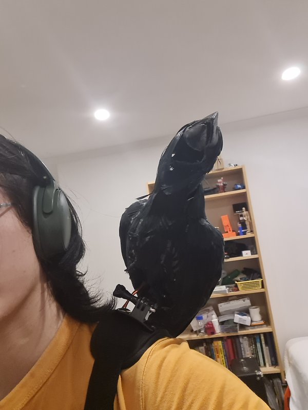
    Inspired by Mr Chicken’s Animatronic Raven, I created set out to create an animatronic crow of my own. At time of writing as well as when I was researching for the project, his DIY kit for it is sold out.

    For the outer shell of the shell, Mr Chicken uses a vacuum formed shell to minimize weight without sacrificing detail or strength. Unfortunately, not only did I not have access to a vacuum former, I also did not have a 3D model let alone a buck to form over. As my 3D sculpting skills were not quite up to the task, I searched online and found this model by YahooJAPAN on Thingiverse. Ideally, I would have used a model that was already articulated, but I could not find any so I would have to slice up the model myself.

    Crow Prototype

    At the time, I wanted to make this model as accessible to as many people as possible which meant 3D printing as much of it as possible and reducing specialty hardware to buy. For the neck, I designed a universal joint which was surprisingly easy to print and effective and instead of screws, the servo motors were fixed in place with zipties which turned out incredibly clean. The head pan and tilt uses paperclip linkages that mimic Mr Chicken‘s design which some slight alterations at the attachment points to accommodate print orientations. Unfortunately, many of the parts require some support material but I kept overhangs to a minimum. There are 4 servos and therefore Degrees of Freedom in my design:

    • Jaw
    • Head Pan
    • Head Tilt
    • Hip

    While I did consider adding a 5th one for wings flapping, I was unable to design a satisfactory mechanism.

    Crow Insides

    Having completed a prototype, I set out to find a more realistic body for the animatronic skeleton I designed. Searching online, I found out that taxidermy is incredibly expensive. I also found out that fake dead crows are a common product people buy and sell for scaring off real ones. While making a bespoke body from scratch may have produced a more realistic end product, this route was too convenient to ignore. Upon delivery, I personally found that the crow did not hold up to close inspection but my mom kept getting frightened everytime she peered into my room so it seemed promising. Peeling feathers off to reuse and carving through glue and plastic was a bit of an ordeal but I managed to fit all the mechanisms and controllers inside. When I tried to put the feathers back where they were supposed to be, since the head had to accommodate a jaw, they did not sit as well as they used to. The crow looks much scruffier than it used to.

    Crow Controller

    To make the design portable, I modified the feet to mimic a GoPro so that I could use a shoulder harness to carry the crow on my shoulder. This was not very comfortable as the bird is slightly unbalanced but is still doable. I had some tire balancing weights from a different project and adding them to the tail section helped a lot. After writing a script to make it periodically gawk and squawk in random directions, I was able to make it completely portable with a power bank that also fit inside the shell.

    With all the added weight, the hip servo was unable to properly lift the body of the crow. Mr Chicken solves the weight problem using much heavier servos than my MG90S’s as well as a heavier spring than my elastic bands. However, after some experimentation, I found out that a 3D printed worm drive mechanism is very feasible and practical. Despite the 180 degree range of the servo, the body is able to swing up and down a good 20 degrees with little effort. Furthermore, due to the nature of worm drives, there’s no need for an elastic band to help hold positions.

    After finalising my design, I reprinted all the insides in black PLA and assembled the crow for the last time (at least for now).

    Crow Skeleton

    Overall, this project has taught me a lot about the feasibility of 3D printed mechanisms and limitations of trying to adapt other people(who are not collaborators)’s designs into custom animatronics. While I feel that I have enough experience robotics design, I hope to one day revisit this project with more propmaking skills to create a more complete looking animatronic.

    Animatronic Crow Demo
    My webhost has a max file size of 2MB

    As I don’t believe this project is in a state which others can replicate it so I will not be sharing the files.

  • 4D Glasses (Proof of Concept)

    I invented (as far as I’m aware) a way to make glasses that let you see a 4 dimensional object in a 2 dimensional image. This project is about an unsuccessful prototype I made.

    Anaglyph 3D

    Bullies were different in the 1950’s

    The classic red and cyan 3D glasses we’ve been wearing since 1853 (you read that correctly) uses a technology called anaglyphs.

    Humans use binocular (2 eyes) vision where each eye recieves a slightly offset image which is percieved by the brain as a single 3D image with depth.

    The illusion of depth can be created through stereoscopy; each eye is shown a separate offset image as they would when looking at a distant object (this is how virtual reality headsets work).

    Anaglyphs are a stereoscopy method where two offset images are coded in 2 different (preferrably chromatically opposite) colors and combined into a single anaglyph image. These can then be separated again for each eye by using 2 corresponding color filters in a pair of glasses.

    In other words, anaglyph glasses add a 3rd dimension, depth, to a 2D image with height and width.

    The 4th Dimension

    My idea is to add an unnamed 4th dimension to an image by having anaglyph glasses that change colors. Humans can only percieve the world in 3D slices so 4th dimensional objects like a tesseract (pictured below) are represented by animated 3D images (although technically it’s a 2D image here); the passage of time lets us follow the 4th axis of a stationary object. Another way to follow along the 4th axis would be to change the colors of anaglyph glasses to view different 3D slices.

    Upon further though, if this project was successful, it would allow 5th dimensional objects to be represented by an animated 4D image. Color changing follows the 4th axis of an object while the passage of time follows the 5th. Although I would need the help of a mathematics animator to create a 4D video of something I can barely conceptualise. I’d love to see a 5-Cube.

    Color LCD Glasses

    The technology behind most electronic displays is Liquid-Crystal Display. These displays contain a liquid-crystal layer, optional color filter layer, polarising filter layer and finally a backlight. If you remove the backlight layer, the screen becomes a translucent panel that can change color which is exactly what I needed.

    Eager to get started, after disassembling a color LCD, I went straight to designing some frames for them. I initially tried to modify these aviators designed by flol3622 (pictured left) but when I tried them on, they were incredibly uncomfortable. It appears that the designer focused only on printability and style without considering comfort; the glasses are very square and do not conform to the human head at all. I decided to modify a design I made years ago (pictured right).

    4D Glasses Frames

    When I initially tried to look through the panels, I thought they were blurry because the liquid crystals weren’t aligned. After I built the frame (pictured at the top of this post) and finally programmed the lenses to change colors, I realised that the panels stay blurry. It’s impossible to make out images through them when pressed up against your eyes.

    4D Glasses LCD Test

    I decided to put the idea on hold for now but I think maybe I’ll try and revisit the idea using a spinning color wheel of filters instead of LCDs.

    As this project was unsuccessful, I will not be publishing the models.